MegaSquirt PNP Gen2 Manual
For models with the v1.3 revision main board
Note that this is the main documentation that is applicable to all MSPNP2 Platform ECUs. For each individual model there is a model-specific addendum to this documentation which addresses the particular installation needs and other unique features of each model of MSPNP2 EMS.
Introduction
What is a MegaSquirtPNP EMS?
The MSPNP2 is a powerful Engine Management
System that completely replaces the stock ECU for racing applications.
If you're not excited, take a moment and GET EXCITED NOW! You now have
the power to fully unleash all of the potential of your engine both with
your current configuration and with any modifications you'll perform in
the future, no matter how extreme you want to take it!
The MegaSquirt PNP takes over the functions the stock ECU provides - fuel
control, ignition control, and various other outputs - and lets you
adjust these yourself by connecting a laptop to the MSPNP2. It is
designed to plug right into the factory harness where the factory ECU
used to be, and if your engine is pretty close to stock, will easily
start your engine just like the factory computer did. You will, however,
want to fine-tune your MSPNP2 in order to get the most out of your car's
potential. After all, this ability to tune the fuel and spark maps to
match your engine is what a standalone EMS is all about.
At its core, the MSPNP2 uses a MicroSquirt Module running MS2/Extra firmware, combined with extension boards designed by DIYAutotune.com. Bowling & Grippo describe the MegaSquirt as "an experimental do-it-yourself programmable electronic fuel injection controller." With MSPNP2, we've already done the experimenting, programming, and wiring needed to make it work with your engine. The MSPNP2 also has a CANBus output that can be used to talk to expansion modules from DIYAutoTune.com or other MegaSquirt product vendors.
For the majority of you, we've packed all the features you'll ever need right into the core of the unit and you'll likely never care to modify anything. We didn't stop with the base feature set of the MegaSquirt but improved upon it.
We've added functions to the MSPNP2 that many original factory ECUs do not have. Some of these are built in and use your existing harness, while others require a few changes to the wiring to access since your factory harness didn't support these features. Since MegaSquirt is a speed density system, it is possible to remove the air flow meter (AFM or MAF) to reduce intake restriction if you'd like to. You can set the rev limiter anywhere you want it, and choose either spark cut or fuel cut based rev limiting on most MSPNP2 applications.
Everything has warning labels...
While most of the warnings will appear in the text discussing what the warning is about, there are a few words of caution before you start installing your MSPNP2.
First, the MSPNP2 is designed for racing applications and other cars that do not need to be emissions legal. It does not use many of the OEM emissions control devices on the engine, nor is its base map tuning calibrated to pass an emissions test.
The MSPNP2 is not waterproof. Then again, neither are most stock ECUs. It's designed to be put in the passenger compartment, not under the hood or in places where it will get rained or splashed on.
We have thoroughly tested the MSPNP2 on multiple cars, and the 'base map' tuning should get a stock engine or a mildly modified engine running with no problem. However if you are using this on a modified engine, the tuning may need significant adjustment to properly run your engine. You'll want to dial in the settings before you really push the engine hard. Engines with significant modifications such as those requiring larger injectors may need several settings changed before they will start at all (though setting it up for larger injectors is easy, and covered in this manual). Even if your car is stock, you'll still need to fine tune the base map for your car to ensure your car is safely tuned as all cars are different. You do not want to damage your engine due to assuming the base map is just fine for your car. It's close, but don't assume it's perfect. GET IT TUNED IN!
The MSPNP2 is designed and tested to work with the stock electronics, wiring harness, and sensors. As a general rule, it will work with almost any modification that works with the stock ECU, and many others that would not have. The only real exception to this is when attempting to use the MSPNP2 with conflicting electronics. For instance, the MSPNP2 should not be used with piggyback tuning systems (but why would you?) or other signal interceptors that effect the sensor readings and/or outputs that the MSPNP2 is using. Attempting to do so may result in unpredictable results, or may simply not work at all and could prevent the MSPNP2 from running your car properly. As long as you are using the factory ignition system, you can add pretty much any modifications available as long as you tune the MSPNP2 to work with them. You are only likely to run into trouble if you try changing the crank trigger/cam angle sensor or ignition module to something that does not work with the stock ECU, and in many cases the MSPNP2 can be adapted to support these as well, though you're getting away from a Plug-N-Play install at that point.
Being a speed density system, your MegaSquirtPNP will let you remove the factory air flow meter. (More details on this below). It calculates the amount of fuel to inject based on RPM and manifold pressure. The MSPNP2 uses a 4 bar MAP sensor that can handle up to 44 psi of boost if you've turbocharged or supercharged your engine, though if you're not running forced induction you're still just fine with this sensor. It just allows for the big plans you may have down the road.
The settings and table values depicted within this document are for illustration purposes only. Refer to the included base maps for the initial settings and values necessary for your application.
Section One: Software Installation and Thumbdrive
A USB thumbdrive is included with your MSPNP2. This thumbdrive contains tuning and analytical software, firmware, base maps, installation guides, and reference manuals. Before installing your new MSPNP2 ECU, it is highly advised that you run and install the software package. Furthermore, it should go without saying that the included documentation should be read, reviewed, and understood before they physical installation of your ECU begins.
To begin, plug the thumbdrive into your computer. It should run automatically, but if it doesn't, browse to the thumbdrive's directory and run the file that includes the model number of your ECU followed by the word "Setup". If you are presented with a dialog asking if you want to allow this application to run, choose "YES". From there, read and follow the prompts as they are presented. When presented with the option to select components, ensure that all check boxes are checked or that "Full Installation" is selected. A program group named "DIYAutoTune" is created in the Start Menu directory. There, you can find links and shortcuts to both installed and online documentation.
TunerStudio
TunerStudio is the software application that is used to tune and configure your MSPNP2 ECU. Documentation on specific tasks for functions can be found with in TunerStudio's help files.
A directory is created in the "My Documents" directly with a folder named "TunerStudioProjects". The included base maps will be loaded to this directory.
MegaLogViewer
MegaLogViewer provides you the ability to analyze and visualize your data to quickly identify problems or opportunities. Load both the data log and tune settings, viewing together. Capture long log files and easily navigate through the data, apply built in analytics, custom formulas and simplified views.
Firmware Reflash
Under normal use, you shouldn't ever have to reflash the MSPNP's firmware. If, however, the firmware does become corrupt, the revision that was preloaded on your ECU is included on the USB thumbdrive and copied to your computer's hard drive. Section four details the process of installing firmware.
Section Two: Basic Installation Overview
As different MSPNP2 models exists, each model is provided with its own installation guide in addition to this general reference. Please read, review, and understand that document to insure proper installation.
Overview of connectors
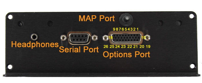
Some of the features on the MSPNP EMS are rather obvious as to why they are there, such as the holes to mount it or the logo on the top to let everyone know how awesome you are due to the EMS you that are running. But it has a few things on it that call for some explanation.
On the back, there is a 26 pin connector. The connector has small numbers cast into it to identify which pin is which. ALL OF THESE CONNECTIONS ARE OPTIONAL AND NOT REQUIRED TO RUN YOUR CAR ON THE MSPNP! These are there keeping the DIY spirit alive, giving you the power to add new capabilities to your vehicle!
- Cam sensor input
- Table switch input
- Clutch Switch
- Tach output
- Chassis Ground
- Switched 12VDC (0.5A Max)
- Boost control solenoid
- Injector A output
- Injector B output
- Knock sensor input
- CANBus high
- CANBus low
- Launch control input
- Spark D output
- Spark C output
- Spark B output
- Spark A output
- Injector C output
- External MAP sensor input
- IAT sensor input
- Oxygen sensor input
- Signal Ground
- 5VDC Vref
- Output 1 relay control (ALED)
- Output 2 relay control (WLED)
- Injector D Output
The 9 pin connector is a serial port for connecting the MSPNP2 to your laptop with the provided tuning cable. If your laptop does not have the matching plug, you will need a USB to serial adapter, we recommend the USB-2920 that we sell at DIYAutoTune.com for best results.
The small connector that looks like it
could be for a set of headphones - well, it is. On engines equipped with
a knock sensor, this allows you to listen to the knock sensor. In most
cases if your vehicle had a factory knock sensor, we've already tied it
in through the factory wiring harness. If your vehicle did NOT have a
factory knock sensor, you can add one, if you like, using the option
connector outlined above.
Some knock sensors have built in filters, and there's a similar filter in the MSPNP2, so it will cut out a portion of the sounds that are not related to engine knock. You will need to take the cover off to adjust the volume (see section 4, Tuning) as well as adjust the knock sensor; we recommend starting at the lowest setting, fully counterclockwise.
There is a small barbed fitting on the back of the MSPNP's case. This is for connecting the MAP sensor. The sensor is designed to work with a rubber hose with around 7/64" - 1/8" inside diameter, which is included in the kit.
The four screws on the back that look like they might be for adjusting something - they're not. Leave them alone.
There are four small holes in the side of the case for viewing indicator LEDs. Looking at the side of the case, from left to right, this what these LEDs do:
- 12 volt power: This light comes on when the ECU has power.
- Logic power (5VDC): Normally, this light comes on whenever the 12 volt power is on. Used mostly for specialized diagnostics.
- Tach pulse: Blinks when you have an RPM signal.
- Knock: Blinks when knock is detected. The more it blinks, the higher the knock level.

Tools required
The MSPNP2 requires very few tools and very little time to install. You will need:
- Timing Light (adjustable or not can be used, adjustable is nice though)
- Philips head screwdriver
- Flathead screwdriver
- Drill for mounting holes - we recommend mounting it with the included #8 sheet metal screws and a 1/8" drill bit.
- A laptop or tuning computer to run the included TunerStudio MS software.
Installation Overview
Installing your MSPNP2 EMS is likely to
take even the first time installer about an hour at most. For the
experienced and/or the professional automotive technician, you're
looking at about an hour long install in most cases.
Please note that
the steps below are just a high-level overview, you must refer to the
vehicle-specific addendum (included in the box with
your MSPNP2 when it shipped) for your vehicle for the specific step by
step guide for your vehicle. Skipping this vehicle specific
documentation could cause you to overlook important steps. That
said, generally speaking here's an overview of the installation process.
-
Locate and remove the factory ECU. Carefully release the harness connector's latching mechanism and unplug the harness.
-
Plug the MSPNP2 ECU into the factory harness in place of the factory ECU you just removed.
-
Route the included 1/8" vacuum hose through your firewall and connect to the MAP sensor barb on the MSPNP2. Connect the other end to the included 'T' fitting and tee it into the vacuum signal used by your fuel pressure regulator.
-
If using a different size injectors than factory, adjust the REQ_FUEL and other settings for this based on the information in Section Four below.
-
Set your base timing according to the MSPNP's documentation. This is of course, VERY important. You must forget everything you know about setting the base timing on the factory ECU except for where you point the timing light. You MUST use the MSPNP's instructions to properly set your timing. The ECU cannot command proper timing until you synchronize it's commanded timing with the actual timing at the crankshaft. It's easy to do, only stressed here due to importance (and the fact that people tend to try and set it like the factory ECU required, and you're not using the factory ECU anymore).
-
Verify all steps in the vehicle specific installation guide for your vehicle have been followed exactly.
-
Start your engine!
-
Tune your MSPNP!
-
Go hit the racetrack!
Section Three: Optional Features
This completes the basic installation of
your MSPNP2. It's now ready for you to start fine-tuning it to match
your particular setup. However, there are several other connections and mods you can
add to use the MSPNP2's extra features. Some examples of this are
MAF/AFM removal to reduce intake restriction, adding an aftermarket
wideband oxygen sensor and controller, or adding a knock sensor to
vehicles that were not equipped with such from the factory.
MAF/AFM Delete
In most cases you can remove the factory MAF or AFM from your vehicle to reduce intake restriction and increase horsepower and torque! See your specific MSPNP2 model's addendum documentation for details for your specific vehicle.
Wideband O2 Sensor and Controller
The MSPNP2 supports many common wideband oxygen sensor systems, including the Innovate Motorsports LC-1 and MTX-L products, the Zietronix ZT-2 and ZT-3 (among others), and most other systems that provide a programmable analog voltage output. You will need to install the controller according to the manufacturer's directions and then connect the MSPNP2 to a programmable analog output from the wideband sensor's controller. You should ground the wideband to the engine block near the factory ECU ground wire to ensure an accurate reading.
There are two ways of connecting the controller to the MSPNP2. You can either connect the analog output to the pin labeled Oxygen Sensor input of the option connector, or you can cut and splice the oxygen sensor signal wire to the analog output. If you use this pin for wideband input, you must disconnect the stock oxygen sensor. Do not ground the oxygen sensor wire if you disconnect it; leave it completely unconnected and taped off if necessary (make sure it can't short to ground or anything else).
After connecting the wideband sensor controller, you will need to change a few settings on the MSPNP2. Section Four has the details of how to change this.
Knock sensing (on cars not equipped with factory knock sensors)
The MSPNP2 is set up to directly accept input from a knock sensor at the option connector on the back of the box. If your sensor is polarized, wire the positive end to pin labeled Knock Sensor input and the negative end to pin labeled Sensor Ground. Most knock sensors have no polarity and can be wired either way. See section 4 for how to tune the knock sensing circuit.
Air Conditioner Idle-Up:
The AC Idle up feature allows the engine idle speed to be increased when the AC compressor is engaged.This feature requires the use of either the Table Switch (formerly PE1) or Launch (Formerly Flex) input to function.The input to be used is jumper selectable and is set by default to Table Switch.
Minimal tuning of the AC Idle Up feature may be required in order for the AC Idle Up to help maintain stable idle when AC is activated, especially on a smaller displacement engine. Luckily, tuning the Idle Up is very straight forward, however before attempting to tune AC Idle Up, the car must first already be properly tuned. Special areas to note include the VE and Spark tables. Further, an idle valve must be installed, functional, and activated in TunerStudio, and idle control must be stable and smooth with AC off. Both PWM type and stepper idle valves are supported by AC Idle Up, and the feature is available for use with either Open Loop (where a duty cycle or valve position is specified, but a target RPM is not) or Closed Loop (where a target RPM is specified) algorithms.
AC Idle Up is activated in TunerStudio under the Startup/Idle tab > Air Conditioning Idleup. The graphic below shows the Idle Up dialog box and outlines the settings.
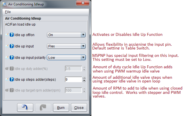
Idle up off/on: This selection enables or disables the Idle Up feature. Off disables, On enables. You must click 'Burn' and powercycle the MSPNP for the change to take effect. It is also advisable as a best practice to save your current tune file (under File > Save Tune As) before enabling or disabling this, or any other, feature.
Idle up input: The default setting is Table Switch, and while most users will never need to change it, this setting allows advanced users reassignment capability of the MSPNP's I/O as to better suit their vehicle if needed. The input pin selected here must correspond to the position of jumper set 3, as shown in the jumper selection table below. This allows the user flexibility in choosing the I/O needs for their application.
Idle up input Polarity: The default setting is Low, and must be left there. This feature allows inverting trigger detection on non-MSPNP Gen2 ECUs. However the MSPNP Gen2 uses a special input filter and must be set to High.
Idle up duty adder (%): Available on vehicles that use a PWM style idle valve with an open loop, “warm up only†idle valve algorithm. This setting increases the PWM idle warmup duty cycle commanded value by the number input in this cell. This is an open loop idle valve setting, so the MSPNP will not seek a commanded RPM. Higher values will result in higher operating idle RPM when Air Conditioning is commanded. Best tuning practice is to start with a small value and increase until stable idle is achieved when Air Conditioning is commanded.
Idle up steps adder (steps): Available on vehicles that use a stepper sytle idle valve when an open loop, “warm up only†idle valve algorithm is requested. This setting increases idle by commanding an additional number of steps as input into this cell. This is an open loop idle valve setting, so the MSPNP will not seek a commanded RPM. Higher values will result in higher operating idle RPM when Air Conditioning is commanded. Best tuning practice is to start with a small value and increase until stable idle is achieved when Air Conditioning is commanded.
Idle up target rpm adder(rpm): Compatible with both PWM and stepper style idle valves. Available when commanding closed loop idle control by adding the value in this cell to the current RPM target in Closed loop idle target RPM curve. For instance, if the current RPM target in the target RPM curve is 900 RPM and the value in the cell is 150, the MSPNP will target 900 RPM when Air Conditioning is not active and 1050 when Air Conditioning is commanded (900 + 150 = 1050). It is imperative that the closed loop idle settings are already tuned before enabling this feature.
Launch control / Flat Shift:
Launch control may be run with either the factory clutch switch or an external switch. If you wish to disable using the clutch switch for launch control, you will need to take the lid off and remove the Launch via Clutch Switch jumper. See the image below (bottom of this section, section 3) for the location of all jumpers on the mainboard.
Launch control may be run with either the factory clutch switch or an external switch. If you are using an external switch for launch control, connect the pin labeled Launch Control Input connector to a switch, and connect the other side of the switch to a chassis ground. Launch control will be active when the switch is closed.
Flat shift requires the use of the clutch switch. It enables a different rev limiter when your foot is on the clutch so you can shift while holding the throttle to the floor.
Flex Fuel:
Instead of launch control, the Launch Control input pin of the option connector may be connected to a GM flex fuel sensor. To enable this, turn off launch control and go to Fuel Settings → Fuel Sensor Settings. Enable flex fuel and set the sensor port to LAUNCH (Formerly Flex). The frequency numbers are set up for a stock GM (or Ford Taurus) fuel composition sensor. The low frequency represents the sensor output with pure gasoline, and the high frequency represents pure ethanol. The MSPNP2 will multiply the pulse width by the Fuel Multiplier % number determined by the measured fuel compensation, and subtract the Timing Correction value. Since the Timing Correction is subtracted, negative numbers will advance the timing.
Table switching:
You can enable table switching for fuel and / or spark tables from the Boost/Advanced → Table Switch Control menu. Set the switch source to Hardware for the table you wish to switch, and the location to Local. This will allow you to use the table switching on the option connector. The alternate table(s) will become active when the pin labeled Table switch input is connected to ground. You can use this to have a second fuel or ignition table for race gas or when a nitrous system is active.
Note that the tables this will switch to are called VE Table 3 and Ignition Table 3 so these are the tables you'll tune for use when Table Switching is activated. Table 2 is used for other functions such as multiple load input.
Boost control:
The Boost control solenoid pin on the option connector is an output for boost control. To use boost control, connect one terminal of an electronic boost control solenoid valve to a 12 volt source that turns on with the ignition, and the other terminal to this pin of the option connector. The boost control solenoid valve plumbs into the line running from the intake to the waste gate.
NOTE-- while many EBC valves could be used, we recommend using the EBC solenoid we sell. This is the valve we have tested with, and have setup the base maps to support. Connect one wire of the boost control valve to a switched 12v source and the other wire to the option connector pin labeled "Boost Control Solenoid". This valve has no polarity though so it can be wired either way without any problems.
Tach Output:
The Tach output pin of the option connector provides a 0-12 volt square-wave signal compatible with many factory and most aftermarket tachometers. Wire your tachometer's trigger wire to this pin.
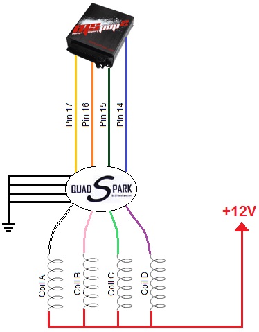
Additional Coil Drivers:
Provisions have been included in the MSPNP2 to remove ignition control from distributor equipped engines to allow ignition from a coil pack. These outputs are logic level (0-5VDC) and able to trigger most standard automotive coils that have an onboard ignitor accepting a 5V logic ignition signal. However, these outputs cannot directly drive a coil without a built-in ignitor. If your coil(s) do not have an onboard ignitor, an external ignitor such as our QuadSpark would need to be installed between the coils and MSPNP2. Below is an example wiring diagram depicting the installation of a QuadSpark with the MSPNP2:
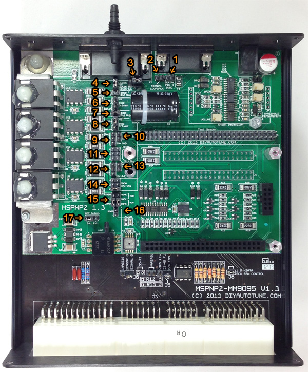
Board Jumpers:
This is what you'll refer to for the locations of all tweakable/adjustable features on the board. In most cases you won't need these at all. In some cases where you're adding features to your vehicle that the factory never supported, or choosing to use a feature configured differently than our default configuration you may need to refer to this.
| Jumper Set |
Name | Jumper Position |
Function | ||
| 1 | Serial Pin 9 5VDC | Off | Serial Port Pin 9 Disconnected (DEFAULT) | ||
| On |
|
SerialPort Pin 9 connected to 5VDC | |||
| 2 | Serial
Loop Back (Diagnostic) |
Off | Serial port normal operation (DEFAULT) | ||
| On |
|
Connects the DB9 TX and RX pins together to allow an "echo" of all communication back to the host. | |||
| 3 | Air Conditioner Idle-Up | Off | Air conditioner idle-up unused | ||
|
TABLE SWITCH (formerly PE1) (TS) |
|
Air conditioner idle-up command connected to TABLE SWITCH (formerly PE1) input (table switch input) | |||
|
FLEX (LC) |
|
Air conditioner idle-up command connected to LAUNCH (Formerly Flex) input (launch control input) | |||
| 4 | Launch via Clutch Switch | Off |
|
OE Clutch Switch Disabled | |
| On |
|
OE Clutch Switch Enabled | |||
| 5 | INJD Inj QTY | Off |
|
One injector controlled by channel D | |
| On |
|
Two injectors controlled by channel D | |||
| 6 | INJD Driver | Off |
|
Injector Channel D Disabled | |
| Batch |
|
Pairs Injector Channel D with Injector Channel B | |||
| Seq |
|
Allows sequential control via PT7 | |||
| 7 | INJC Inj QTY | Off |
|
One injector controlled by channel C | |
| On |
|
Two injectors controlled by channel C | |||
| 8 | INJC Driver | Off |
|
Injector Channel C Disabled | |
| Batch |
|
Pairs Injector Channel C with Injector Channel A | |||
| Seq |
|
Allows sequential control via PT6 | |||
| 9 | IGN B/D | Off |
|
Ignition Channel D Disabled | |
| WS |
|
Pairs Ignition Channel B with Ignition Channel D for Wasted Spark control | |||
| Seq |
|
Allows sequential control via Output 1 (ALED) | |||
| 10 | IGN B/D PullUp Ena |
Off |
|
Spark Channel D pull-up resistor disabled | |
| On |
|
Spark Channel D pull-up resistor enabled | |||
| 11 | INJB Inj Qty | Off |
|
One injector connected to Injector Channel B | |
| 2 |
|
Two injectors connected to Injector Channel B | |||
| 3 |
|
Three injectors connected to Injector Channel B | |||
| 4 |
|
Four injectors connected to Injector Channel B | |||
| 12 | IGN A/C | Off |
|
Ignition Channel C Disabled | |
| WS |
|
Pairs Ignition Channel C with Ignition Channel A for Wasted Spark control | |||
| SeQ |
|
Allows sequential control via Output 2 (WLED) | |||
| 13 | IGN A/C PullUp Ena |
Off |
|
Spark Channel C pull-up resistor disabled | |
| On |
|
Spark Channel C pull-up resistor enabled | |||
| 14 | INJA Inj Qty | Off |
|
One injector controlled by channel A | |
| 2 |
|
Two injectors controlled by channel A | |||
| 3 |
|
Three injectors controlled by channel A | |||
| 4 |
|
Four injectors controlled by channel A | |||
| 15 | Knock Detector Mode | Off |
|
Invalid | |
| TRSH ADC1 BARO |
|
AKNK ADC2 IKNK |
Normal (DEFAULT) | ||
| TRSH ADC1 BARO |
|
AKNK ADC2 IKNK |
Test | ||
|
|
Reserved | ||||
|
|
Reserved | ||||
| 16 | BOOT | Off |
|
Normal operation (DEFAULT) | |
| On |
|
To be used when upgrading firmware. | |||
| 17 | MAP Select | Off |
|
Invalid Selection | |
| Int. |
|
Use the on-board, internal 4-bar MAP sensor | |||
| Ext. |
|
Use an external MAP sensor that is connected to pin 19 on the options connector. | |||
Section Four: Tuning
Think of this guide as sort of a quick start guide, as well as an explanation of the unique features of the MSPNP2. With the MegaSquirtPNP, tuning is not very different from other MegaSquirt varieties, or most other aftermarket standalone ECUs for that matter. If you've tuned another EMS system before, this process will be very familiar as the fuel and ignition tables will be very similar. You can find in-depth information on tuning MegaSquirt in the MS2/Extra Manuals, available online at MSExtra.com
Working with MSQ files (TunerStudio Maps)
TunerStudio stores the information from MegaSquirt in MSQ files. The MSQ file contains all of the adjustments and settings needed to run MegaSquirt on a particular engine. These let you back up your tuning or compare your settings with other MegaSquirt users.
The MSPNP2 thumbdrive for your vehicle comes with a base MSQ file. We've tested this map out on a stock vehicle, and it should get most cars with basic bolt-ons to start up and run with no problem. Even if your car is stock, you will want to fine-tune it to your particular engine, as every car varies just a bit. If you've added any significant modifications, you will definitely want to do some good tuning before really pushing your engine to its limits. But if you find yourself getting lost and having trouble with your tuning, you can go back and reload this default tune to make things work again as a baseline.
The base map is intended as just that however: a 'base' map. It was tuned on 93 octane fuel, and in theory is somewhat conservative. Fuel is different from gas station to gas station, and pump to pump, so what is in theory conservative here may be aggressive on your fuel. AT A MINIMUM RUN THE BEST PUMP FUEL AVAILABLE, AND GET IT TUNED IN, AND KEEP RUNNING THAT FUEL OR BETTER. On a stock car EXACTLY like ours, in EXACTLY the same condition, this map should make similar power to stock, maybe a bit better, though we recommend only running premium fuel, and getting the system properly tuned for your car as soon as possible. With this EMS you have full control of all aspects of engine management on your vehicle. You will find you have excellent results when properly tuned. Though giving you that level of control means you also have the power to tune your engine very badly if you improperly tune things, and could even melt down your engine in a hurry if you don't tune the engine properly. The power to tune is just that, very powerful Do it right the first time, and if you're not confident in your ability to do so, get a professional tuner to assist you on a load-bearing steady state dyno where the maps can be properly tuned in for your car. Once that's done by a qualified tuner, you can rest assured that your engine is safely making all of the power that it can make with optimum drivability.
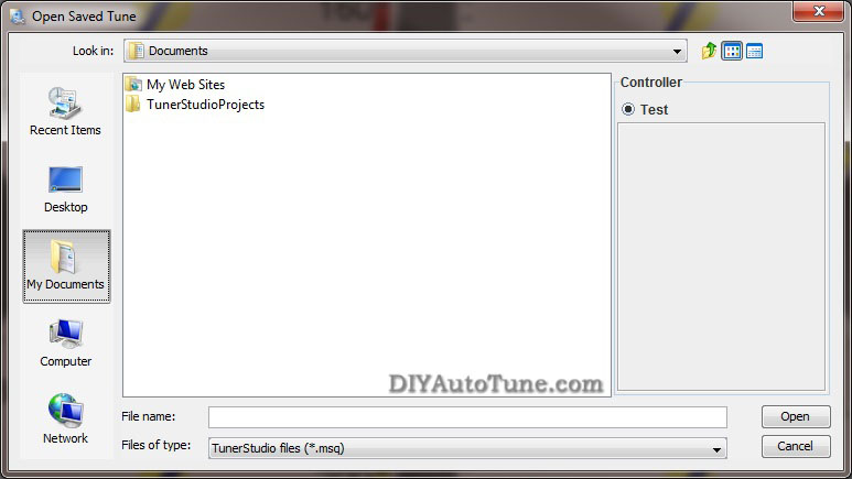
If you go to File → Open Tune (MSQ) in TunerStudio, you can open a MSQ file and it will load it into your MegaSquirtPNP. This will overwrite all the settings you currently have saved in the MegaSquirtPNP's memory. TunerStudio will confirm that you want to do this. If you see a dialog box appear with a message that there were warnings when you open the MSQ file, you should probably cancel this until you can investigate further. Feel free to contact our support team and we'll help you quickly determine what may be causing the warning.
If you want to open a file just to examine it, the safest way is to open it with the MSPNP2 disconnected. Then you can go to the File menu and select Work Offline. You can then examine the settings in the MSQ file without loading it onto your MegaSquirtPNP.
The "Save Tune" command under the File menu will save your settings. TunerStudio will automatically suggest a name based on the time you have saved the file, or you can specify your own file names. We recommend you save frequently during the tuning process so that you can always revert back if you make a change and find you need to back out.
You can share MSQ files with other MegaSquirtPNP users, though it can be risky business if you are not careful. It's easier and generally safer to copy a MSQ file from another MSPNP2 user running the same model MSPNP2 you are running, but you can also use maps from standard MegaSquirt if you first set the spark, input and output settings to match those in the MSPNP2 base map. There are a few words of caution when sharing MSQ files. First, you will need to make sure it is from a similar version of MS2/Extra, 2.1.0 or later. Do not try loading any MSQs from MS1 or MS3 variants. You will see a warning if you try to load one from an incompatible firmware version; don't ignore this warning.
Second, non-MSPNP2 MegaSquirt (such as a DIY MS model) may use different outputs from a MSPNP2. Even the MSPNP's cousin the DIYPNP is not always an exact match. You will want to check to make sure all outputs are assigned to the same channels before loading a non-PNP MegaSquirt map into your MSPNP2. If these are not set correctly, you may damage your ignition system or accidentally disable certain features of the MSPNP2.
The last potential source of trouble when sharing MSQ files is that a different owner's MSQ file may not be right for your engine. It may be tuned for an engine with different modifications, or may have a few mistakes in it's tuning. Loading an untested/untuned MSQ file just before a race and going out for a few laps without tuning it can be a recipe for disaster.
If you are not 100% sure of what you are doing, then don't. You risk burning your ignitor and coil and/or damaging your ECU. The base map provided is very good and will get you well on your way to a well tuned car, you will need to fine tune your car no matter where you get your 'base map' from, so you're best bet is to put your car on the dyno, using our base map to start from, and dial it in on your car.... no guesswork needed!
Loading firmware
It is very rare to need to load firmware to a Gen 2 MSPNP2 as you do NOT need to change firmware to handle sensor calibration as was needed with the Gen1 MSPNP2 units. You will only need to reflash firmware if you are upgrading to a newer firmware release, or have managed to damage your firmware by overwriting with an incompatible MSQ file, like we just warned you about in the previous paragraphs. If you need to load firmware, here's how to do it. Be sure to unplug your ignition module (or coils) before loading firmware, and do not plug them back in until you have loaded a MSQ file for your car. FAILURE TO DO THIS CAN DAMAGE YOUR COILS OR IGNITION MODULE.
-
Connect the MSPNP2 to your computer with the serial port.
-
Disconnect your ignition module.
-
Power up the MSPNP2 on the car.
-
Go into the Program Files -> DIYAutoTune -> Tools and open the MS2/Extra folder that matches the firmware you wish to load to your MSPNP2. If TunerStudio or other tuning software is running, close it.
-
Open the program called download-MS2-firmware.exe.
-
This program will first ask you a couple of questions about loading the code; tell it you have a MSPNP2 and which COM port you are using. Specify that you are not upgrading from standard B&G firmware. Caution: Loading the MS2/Extra version for a MegaSquirt 2 V3.0 / V3.57 will cause problems with the ignition output, and may even damage your ignition system. Be sure you load it with the MSPNP2 version of the firmware.
-
The utility will load the MS2/Extra code. It will end with a message stating that verification has succeeded. You can now connect to the MSPNP with TunerStudio again.
Settings that should not be changed
The MSPNP2 does not lock you out of any of the settings. As the core MegaSquirt EMS platform is very powerful and designed to work on just about any engine running just about any sensors and ignition system available, there are several settings used to configure the ECU in order to allow the use of these sensors and ignition systems. These are critical settings, and installing a non-PNP MegaSquirt EMS must be researched and configured for each vehicle. We've however taken the guesswork out of this with the MSPNP2, and you DON'T want to change these settings. We've configured the MSPNP2 for your ignition already, and changing some of these settings could cause your MSPNP2 to stop working with your engine, or worse, could even damage your engine or electronics. In addition, there are several settings and options for features not enabled on the MSPNP2. Here are some areas which you should not adjust, as well as some settings that should only be adjusted if you have modified your ECU to enable them.
Ignition Settings you don't want to touch unless you know what you're doing
With stock ignition system components (crank and/or cam trigger wheels, ignition coils, ignitors, etc.), many of the ignition settings need to be left as they are. The only reason to adjust any of the ignition settings (including trigger wheel settings and rotary settings) beyond the spark table are to set the base timing, which you must always do once prior to driving your vehicle on the MSPNP2. If you are changing the type of coil you are running to an aftermarket coil or ignition module (ignitor) you might need to change the dwell settings. One other scenario in which you might need to adjust these is if you are converting from a distributor to a distributorless ignition.
Fuel Settings you don't want to touch unless you know what you're doing
Do not enable PWM current limiting for the injectors - the MSPNP2 firmware just ignores this as it's not needed with the addition of the Peak-N-Hold injector circuitry integrated into your MegaSquirtPNP.
Changes to the staged injection or sequential parameters may only work if you have made the appropriate changes to the injector wiring. This is getting away from the PNP (Plug-N-Play) aspect of this product by allowing you to upgrade your ignition system and fueling beyond what the factory allowed for, and is of course not required to use the product on a vehicle with a stock ignition and fuel system. Input and output ports, such as those under the Output Port Settings, Boost Control, and Tacho Output, are hardwired and should not be changed except as specified in the manual. There is also a reference to nitrous control, although nitrous outputs are not installed on the MSPNP2. (You may, however, use the table switching input to use a different fuel and spark table for nitrous.)
Idle Control Valve Settings you don't want to touch unless you know what you're doing
You also do not want to change the settings for the type of idle valve unless you actually change out your idle valve to a different valve. We've pre-configured the base idle valve settings to control the factory idle valve on your vehicle's engine. While you may need to fine tune the closed loop control settings, or the PWM Warm-up settings, you don't need to change the base configuration such as the idle valve frequency.
Settings you DO want to change/tune
Verifying and Adjusting Base Timing
Because the factory ECU is no longer in control of ignition timing, it will be necessary to make checks to ensure the MSPNP is accurately delivering the proper timing. Improper ignition advance can cause engine damage if improperly set or is left unchecked.
The MSPNP will have a base ignition map loaded and ready to use. However, it is necessary to ensure that the timing advance being commanded by the MegaSquirt is in sync with what the engine is actually seeing. These steps will require the use of a timing light and a laptop with a copy of TunerStudio running.
-
Following the manufacturer's directions, carefully install a timing light on the cylinder #1 spark plug wire. Use all due caution here, as secondary ignition voltage can be as high as 100,000 volts or more. Also ensure that the timing light's cords can not get tangled in a moving engine or burned on hot components.
-
Make sure your tuning laptop is connected to your MSPNP and start your vehicle. If you have not already done so, open TunerStudio MS or TunerStudio Lite tuning software that you have already downloaded and installed on your laptop. Make sure that your laptop connects to the MSPNP and you are online.
-
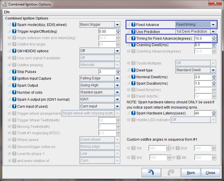
Navigate to Ignition Settings -> Ignition Options/Decoder Wheel . If "Fixed Advance" is set to "Use Table", set it to "Fixed Timing". This will tell the MegaSquirt to ignore our Ignition Table and hold a fixed advance. Enter a value in Timing for Fixed Advance (degrees). This value is a static value that the MegaSquirt will use to command ignition timing. 10.0 is the default, but anywhere between 10.0-15.0 degrees is reasonable. Burn these changes and close this menu. (Ignore the sections not highlighted in blue rectangles.)
-
Use a timing light to confirm you have 10 degrees of timing on the crank pulley. If you have more timing, increase the "Trigger Angle" value. If you have less, decrease the number. For example, if your trigger angle is 60 degrees and you're seeing 15 degrees of timing, change "Trigger Angle" to 55 degrees to bring the timing to a real 10 degrees. Note that these changes only take effect when you turn the ECU off and back on again.
-
Now that the base timing is set, the MSPNP2 can now bet set to command timing advance from the ignition table. If it isn't open already, select Ignition Settings -> Ignition Options/Decoder Wheel. Change "Fixed Advance" back to "Use Table". Burn and close this menu. The MSPNP is now advancing based on your ignition table.
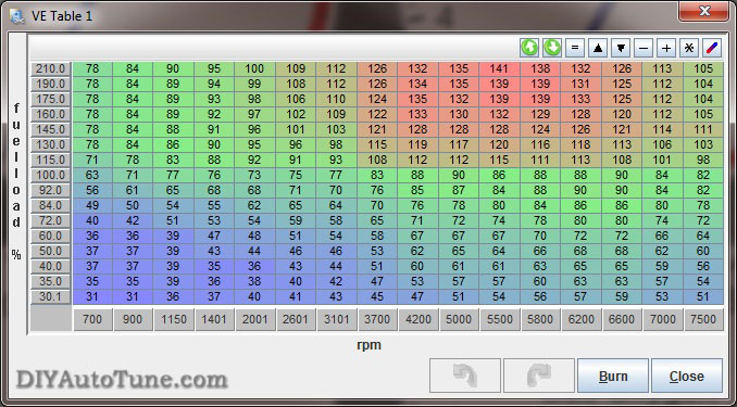
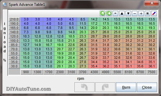
Fuel (VE) and Ignition Tables
The two main controls, the spark and VE (fuel) tables, are tuned with a similar interface and in the same manner. Both are located under the Basic Setup menu. You can access the table directly and fill in values numerically, or you can toggle the checkbox in the top . When viewing the table directly, note that you can change the bins on the load and RPM axes. You can move these around to accommodate boost or a higher RPM limit, or space a couple bins more closely if you run into any spots that are difficult to tune. The engine load % corresponds to manifold pressure when running speed density (the default for our maps). 100% load is equal to 100 kPa, so engines running forced induction will go over 100% load.
The spark advance table gives the spark advance in degrees as a function of engine RPM and manifold absolute pressure. The best way to tune this table is on a steady-state chassis dynamometer, but you can often get significant power gains by dialing in the ignition on an inertia dyno.
The VE table represents a correction factor from how much fuel the MegaSquirt would inject if you were running a stoichiometric (14.7:1) air to fuel ratio, and the engine actually pulled in a volume of air equal to its own displacement every engine cycle at the temperature and pressure that MegaSquirt measures. You use the VE table to correct for both the engine's actual volumetric efficiency and to change the air/fuel ratio to richer or leaner as the engine requires. Increase the number in a cell to add more fuel at that MAP / RPM combination, and decrease the number to inject less fuel.
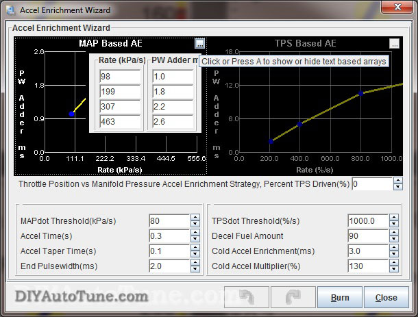
Acceleration Enrichments
The acceleration wizard under the Accel Enrich menu lets you adjust the amount of fuel added when you suddenly hit the gas pedal. There are two graphs, one for MAP based and one for TPS based. The "PW Adder" value is how much extra injector pulse width to add, while the rate number is the change in kPa per second or throttle opening percent per second respectively. For example, 100% TPS per second equals the amount of throttle opening speed needed to go from fully closed throttle to fully open in one second. You can adjust the extra pulse width to increase or decrease the amount of fuel added based on how quickly the manifold pressure changes. The Acceleration Enrichment Settings lets you phase out the acceleration enrichment as RPM comes up. It will start reducing acceleration enrichment when you reach the Low RPM Threshold value, and turn it off completely above the High RPM Threshold value.
The MSPNP2 also offers an acceleration enrichment mode called Enhanced Acceleration Enrichment. Instead of behaving like the accelerator pump on a carburetor, this feature uses computerized models to determine and accommodate for the fuel that gets stuck to the walls of your intake manifold and allows for very precise tuning. You must have the VE table dialed in correctly in all areas, including overrun and low RPM, for Enhanced Acceleration Enrichment to work correctly. A complete guide to tuning Enhanced Acceleration Enrichment is available here: https://www.megasquirtpnp.com/eae
Rev Limiter
MSPNP2 incorporates a two stage rev limiter, accessible under Basic Setup → Rev Limiter. The soft rev limit simply pulls the amount of timing listed as Maximum Retard from the timing table, while the hard cut can shut down the ignition, fuel, or both. This behavior is all configurable on this screen. You choose whether you want fuel cut, or spark retard at a certain RPM followed by fuel cut a couple hundred RPM higher, or any number of possible configurations. The latter is probably the most common configuration, allowing the power to drop off just before redline, and then fuel cut at whatever redline you choose. Note that a fuel cut will not run your engine lean, it will completely CUT the fuel so that no fuel is flowing. This has proven to be a safe method for use as a rev limiter on N/A and forced induction vehicles.
As a general rule, you should only use the spark cut rev limiter by itself if the car is not equipped with a catalytic converter. Cars with catalytic converters should use the fuel cut rev limiter, either on its own or in combination with spark cut. Turning off the ignition without cutting the fuel will dump raw fuel into the exhaust and can damage the catalytic converter.
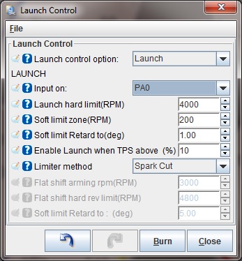
Launch Control
The launch control is based on a rev limiter. This is configured from the Boost/Advanced → Launch Control Control dialog. Often the best way to control this is with the stock clutch switch which opens/closes a circuit based on the clutch pedal position. Note that often this circuit also runs through the neutral safety switch on manual transmission vehicles. This means that if you turn launch control on using the stock clutch switch, it will activate when the transmission is in neutral or when you push down the clutch. So when the trans is in neutral, you'll have a launch control rev limiter. When you push in the clutch and put the trans into first gear, you'll also have a launch control rev limiter (which is when you want it) every time after you first put the car in gear and take your foot off the clutch. When you have the launch control active, the rev limits drop to the limits specified on the launch control screen, letting you rev the engine up to a fixed RPM that you can adjust. When you release the switch, the rev limit is removed and you take off nice and controlled.
Settings to Change for Modifications (injectors/intake/exhaust/cams/boost/etc.)
Many mods will simply require tuning the VE and spark tables to fit. Modifications to the sensors and fuel system, however, require specific changes to the settings. Here are the recommended changes for some common modifications.
Fuel Injector Compatibility
The MSPNP2 can drive a wide variety of injectors, including both high and low impedance. Note that the MSPNP2 ECU's case will run slightly warmer when controlling low impedance injectors. This is normal and nothing to be concerned about.
Changing to a different Fuel Injector Size
When you change the injector size, MegaSquirt can handle most of the adjustments with just one variable, Required Fuel (aka REQ_Fuel), which sets the base pulse width. TunerStudio can calculate this value automatically for you. To do this, open Basic/Load Settings → Engine Constants → Required Fuel. From there you just need to enter your engine size, number of cylinders and injector size, as well as 14.7 for the air/fuel ratio. Don't be concerned if the info in this dialog doesn't match you engine when you first open it up, it doesn't store your info here, just uses it to calculate the new REQ_Fuel number.
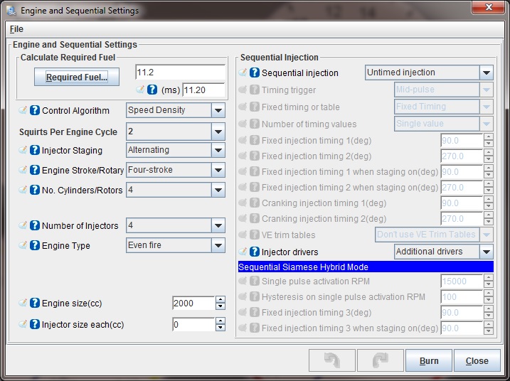
There are a few settings which need to be tweaked when changing injector size that do not adjust when you change REQ_FUEL as they are static pulse width (PW) settings, so you will need to adjust these by hand. The acceleration enrichment settings will probably need to be retuned for the new injectors. For instance if you double your injector size, start at approximately half the acceleration enrichment pulse width and fine tune from there. You may also need to adjust the injector opening time under Injector Characteristics. This number is more properly termed injector dead time, as it is the opening time minus the closing time.
After swapping in new injectors and making these adjustments, it's a good idea to make sure your air-fuel ratios are still where they should be. Sometimes the VE table will need a bit of fine tuning due to differences in the way injectors behave, and it's also a math check for the changes you just made. Make sure the air-fuel ratios are good before pushing the engine hard after an injector swap.
Wideband oxygen sensors
MSPNP2 supports many common wideband oxygen sensor systems, including the Innovate Motorsports LC-1 and MTX-L line, the Zietronix ZT-2 and ZT-3 (among others), and most other systems that provide a programmable analog voltage output. There are a few changes needed to the software settings in order to properly display and use the wideband sensor input properly.
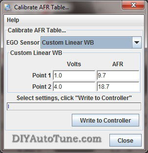
To switch TunerStudio over to a wideband, go to File → Project Properties. Select the Settings tab and set Oxygen Sensor / Display to Wideband, then click OK. Then you will need to tell the MSPNP2 what voltage output your wideband controller sends. You do this under Tools → Calibrate AFR Table. Most common wideband sensors can be selected from the drop-down menu. If you don't see yours, or your controller has been set to a nonstandard curve, you may select "Custom Linear WB" and enter in its voltage and air/fuel ratio at two points to match a linear output from your wideband to your MSPNP2 ECU.
Once you have set the MSPNP2 for your sensor calibration, there are a few other settings you will need to make. You will find most of these in the EGO Control option under the Basic Setup menu. You will need to set the EGO Sensor Type to Single Wide Band. The MegaSquirt will try to maintain the air-fuel ratio specified under AFR Table 1 when running in closed loop mode. The Controller Authority setting limits how much it can change the amount of fuel delivered, so that a faulty sensor can only cause the engine to be off by a small amount. This page also lets you disable the EGO control at full throttle, idle, or when the engine is cold.
The registered version of TunerStudio is also able to tune the VE tables on its own, based on inputs from a wideband sensor. This feature is called VE Analyze Live. The software will adjust the VE tables in a limited range to make the air-fuel ratio match your target settings. Use this feature with caution and make sure your targets and sensor readings are correct before you enable it. You will usually still need to do fine tuning by hand. VE Analyze Live can be used with a narrow band but only to target 14.7:1.
Tuning for Boost
When setting up MSPNP2 on a boosted engine, you won't have to change very many settings other than properly tuning the VE and Ignition tables for the additional airflow and load. Start with making sure your VE and spark tables go up to the maximum amount of boost you plan to run. Since boost is gauge pressure and MegaSquirt works in absolute pressure, this table will help you convert the amount of boost to the maximum KPA level. These values go just a little above the maximum boost setting. Note that this table assumes sea level pressures as ambient.
-
Naturally aspirated: ~100 kPa (at sea level)
-
5 psi: ~135 kPa
-
10 psi: ~170 kPa
-
15 psi: ~204 kPa
-
20 psi: ~238 kPa
-
30 psi: ~307 kPa
-
40 psi: ~376 kPa
-
44 psi: ~404 kPa
The MSPNP2 is equipped with a 4 bar MAP sensor, so the maximum amount of boost it can read is 44 psi of boost. While higher amounts of boost will not damage the sensor in most cases, it can damage your engine if you do not tune for it. The MSPNP2 will not know to add any more fuel above 44psi to compensate because it cannot detect the extra air/pressure, which can result in dangerous lean conditions if you boost beyond that point. If you need a MAP sensor capable of reading higher than 44psi please contact our tech support, we can help!
Since MSPNP2 is a speed density system, you do not need to recirculate the air in the intake (though you can if you want to). If you prefer, you can go ahead and install a monster blow off valve and vent it to the atmosphere without worrying about having it throwing off your measurements.
Overboost Protection
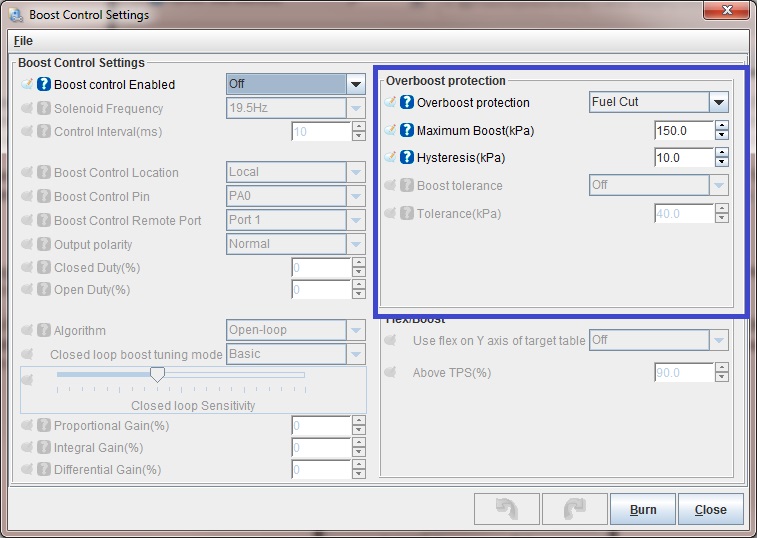
Overboost protection is available under the Extended menu. The MSPNP2 base map for factory naturally aspirated vehicles has a default Overboost Protection limit set of 150 kPa which is a bit above 7 psi (depending on ambient pressure in your area). This limit is there to prevent an overboost condition and to protect your motor. If you've added a supercharger or turbocharger to the engine you'll need to adjust this limit to be a bit above the amount of boost you want to run.
When the threshold is reached, injector PW (pulse width) will be cut to 0 for a split second until MAP (manifold pressure) drops back below the limit if overboost protection is turned on (and configured to fuel cut, which is typically how it would be setup). Therefore with the default settings on a factory naturally aspirated vehicle, if you try to boost too near to 150 kPa you will feel the engine cut out when Overboost Protection kicks in. This can feel like a single cut, or it can feel like the car is erratically cutting out and bucking if you stay on the throttle and continue to bounce off the limiter. The Hysteresis value lets you determine how far the boost pressure has to drop before the overboost protection is turned off allowing the injectors to fire again. This 150kpa Overboost Protection limit, and the hysteresis, are very easy to configure in the tuning software on the Overboost Protection dialog under the Extended Menu in TunerStudio MS.
NOTE-- for factory forced induction cars (supercharger or turbo) the default boost cut limit will vary by model. Typically this will be about 20% above the factory boost levels normally seen on the vehicle model. Please see the vehicle specific docs for your MSPNP2 model/vehicle for further details on the default limit on your car. Tuning is the same as above.
Boost Control
The MSPNP2 has an electronic boost control feature supporting open and closed loop boost control. Once you have wired this up, you can enable boost control in TunerStudio. In open loop mode, the boost control solenoid puts out a signal at a fixed duty cycle (that is, a percentage of time the solenoid is open) as a function of RPM and the throttle position sensor. This is a bit easier to tune and will generally keep the boost right where you set it, but can drift a psi or two with dramatic changes in air temperature and other variables. You'd be most likely to notice this if for instance you had tuned the car on a 80degF day for 15psi of boost, then drove it on the 32degF day. In that case you might see an extra pound or two of boost. Closed loop boost control is a bit more complicated to tune, but when properly setup allows the ECU target and correct to a specific boost pressure regardless of ambient air temps and other variables that come into play.
NOTE-- while many EBC valves could be used, we recommend using the EBC solenoid available from DIYAutoTune.com. This is the valve we have tested with, and have setup the base maps to support by default.
When running boost control, you'll set up the basic parameters for the valve under the Boost Control screen in the Advanced menu. For our EBC solenoid, we recommend a frequency of 19.5 Hz and a control interval of 20 ms. The boost control pin is always PA0. The Output Polarity setting is Normal. The duty cycles can be a little confusing at first glance: They refer to waste gate opening, not solenoid opening. Set fully closed to 100% duty cycle (this means an open valve applying maximum pressure to the waste gate) and fully open to 0% duty cycle (a closed valve will send no pressure to the waste gate).
Tuning Open Loop Boost Control
If you're using open loop boost control, you'll next need to tune the 'Boost Duty Target' table. And easy way to do this is to start by selecting the whole table (drag a box over all cells), click the "=" button, and set the cells to 10%. Normally, 10% duty cycle won't increase your boost at all, but when you test, watch closely, you may need to use a lower number for your baseline, maybe even all 0's.
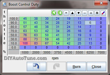
Burn this and try it. See if your boost increases ANY at all over your waste gate only boost levels. Then slowly raise the whole table maybe 5-10% at a time (again, multi-select and fill the whole table is the easy way). Burn it and test it. Datalog this and compare how much boost you made to the prior pull. The pulls need to be in the same gear with all conditions identical, preferably on a dyno, though a track could work if you have a long consistent straight that you can pull 3rd or 4th gear from before the turbo spools (maybe 2000rpm) on up to redline, repeatedly, in a safe environment. You're looking for when you start making more boost. When you do then you can start fine tuning at different RPM ranges. Adding a little more here, pulling a little out there, moving around the RPM columns to make it do what you want it to do, reviewing your logs in MegaLogViewer to see what the results of each pull are. Notice in our example table below, we've got 100%DC in the first column. That's an attempt at making the turbo spool as fast as possible. The GT2560 turbo in our 91 Miata shop car is fully spooled to 13.7psi by about 3500rpm. In order to keep it from spiking though we had to bring the duty cycle way down to 45 by 3200 rpm, then after that we just 'gave it what it needed' to keep the boost at about 13.7psi across the rest of the rpm range all the way to redline. You can see in this table at higher revs it took less DC as the turbo was wanting to make more boost so we had to pull the boost controller back some to control it.
Bottom line, start at low duty cycles, make small changes, and analyze the results of each pull. Remember that as you add boost you're getting into previously untuned areas of your fuel and spark tables and you'll need to adjust those as you go.
If your car has a variable TPS (throttle position sensor) then you can also adjust open loop boost duty cycle based on throttle position, making the waste gate increase or decrease boost at lower throttle positions. Typically you'd reduce DC at lower throttle positions, such as in the cruising speed range where you don't want the turbo boosting to the moon.
Tuning Closed Loop Boost Control
We recommend tuning the open loop boost control before you attempt to tune closed loop boost control. To tune closed loop boost control, first set up the boost control target table. You will enter the desired kPa reading as a function of throttle position and RPM. You should not enter in any values lower than waste gate pressure as the valve cannot reduce boost any further, your mechanical wastegate's pressure is the baseline and can only be added to by electronic boost control. Next you will tune the PID values under Boost Control Settings to make it better hit these targets.
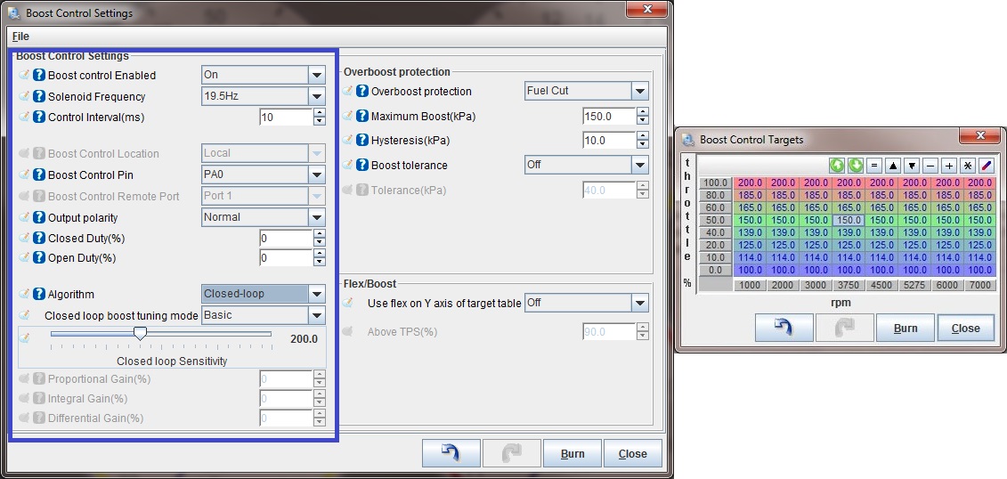
We'd recommend starting to tune CLEBC (closed loop electronic boost control) at a lower boost pressure than you ultimately intend to run. This will allow you to get a handle on tuning this feature prior to running more serious pressures. Before you start, make sure you've adjusted your VE and ignition tables conservatively around and above the boost pressures you are targeting, that means keep the fuel a bit richer than you expect to need, and the ignition a bit retarded from where you expect it to be. To tune the PID parameters, start with 100% proportional gain, 0% integral gain and 0% differential gain. If the boost overshoots above its target get out of the loud pedal quickly, and increase the proportional gain. If it does not spike, you may reduce the proportional gain until you get just a very small amount of overshoot. Leave the proportional gain there. At this point, the boost is likely to creep up slowly after reaching the target. Add a bit more integral gain until the boost stays on target, then increase differential gain until you have minimal overshoot when the turbo first spools up. At this point the boost should track right along with the target boost pressure you've set your MSPNP2 to target.
Datalogging
TunerStudio can log the MSPNP2's input and output readings to help you dial in your tune, and it can also be a great diagnostic tool. You can activate this by pressing Alt-L or going to the Datalogging menu and selecting Start Logging. You will be prompted to enter a file name and save it. TunerStudio will start recording after you save the file, and continue saving a data log until you close TunerStudio or turn the logging off. You can then play back these logs with MegaLogViewer to see if your tuning delivers the right air-fuel ratios throughout the RPM range, to monitor commanded ignition timing through the pull, or any number of variables that can help you properly tune your engine. Things such as ignition dwell, manifold pressure & boost, air/fuel ratio, idle valve duty cycle, boost control valve duty cycle, and many other variables can be monitored here. This is an EXCELLENT tuning tool, and is also an invaluable troubleshooting tool should the need arise.
Knock Sensing
Your MSPNP2 is equipped with an adjustable knock circuit with a built-in audio output to listen to the knock sensor (similar to a set of detcans). There are a total of four adjustment points accessible by removing the top cover. See the jumper diagram at the bottom of Section 3 (above) for locations of these.
The "Volume" adjustment is only for the headphones; it will not affect any of the other settings. This adjusts the headphone volume. The sound on the headphones has been run through a band pass filter to remove much of the engine background noise. This also affects how knock sounds as it is centered on the fundamental knock frequency. You will not hear a "rocks in a coffee can" type sound if the engine is knocking. Instead, the sound will be more like a very high pitched ringing, chirping, or scratching sound. Clockwise increases the volume, be very careful with this as it may need to be adjusted to work properly with the headphones you use, and is capable of a fairly loud volume level depending on your headphones.
The circuit works by generating a threshold voltage based on RPM, and seeing if the signal from the knock sensor goes over the voltage. The "Gain" adjustment knob lets you amplify the signal before it is compared to a threshold voltage. Turning the knob clockwise increases the amplification. The "Start" knob sets the voltage at zero RPM, while the "Slope" knob sets the amount the voltage increases as RPM increases. The threshold voltage can be measured by checking the "Threshold" test point on the board, but it can also be read through TunerStudio.
Here is how we recommend adjusting the knock threshold on a dyno. Note this requires a few steps in order to use the ECUs data logging/gauge capability to capture the noise floor on your specific vehicle so that we can then monitor for any noise above that floor.
-
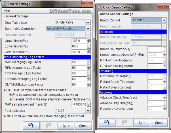
Under Basic/Load Settings → General Control , set Barometric Correction to "Initial MAP Reading."
-
Under Ignition Settings → Knock Sensor Settings , set Knock Control to Disabled.
-
Inside the case, place the jumper 15 (See jumper tabel above) in the "Test" position (to the right).
-
Right click on one of the gauges, and change it to ADC 6 under Sensor Inputs 2. This gauge will give you your threshold voltage.
-
Right click on a second gauge, and change it to ADC 7 under Sensor Inputs 2. This gauge will give you the peak voltage reported by the knock sensor.
-
Set the spark table to a conservative value that is known not to produce knock. (If at any point you hear it knocking during this test through the headphone jack, reduce the spark advance further.)
-
Conduct a full throttle dyno pull (assuming and only if the ECU is fully tuned for the car) and watch the ADC 6 and ADC 7 gauges. You will want to keep the ADC6 gauge just a little under the value reported on the ADC7 gauge - the closer they are together, the more sensitive the system will be to knock, although getting them too close together or having ADC6 exceed ADC7 will result in false knock readings. Adjust the Start and Slope pots as needed to get ADC6 to track closely with ADC7 without exceeding it.
-
Inside the case, place the jumper at JS6 back in the "Run" position (to the left).
-
Re-enable knock sensing and real time barometric correction.
Going to the Dyno
Everyone should properly dyno tune any standalone EMS to get the most out of their car and the MSPNP2 is no different. However, dyno time is very expensive diagnostic time - you want to have your car sorted before you go. You don't want to show up to the dyno with your MSPNP2 in the box along with your set of 550cc injectors and new boost controller....that's asking for trouble. Go ahead and get the car running on the configuration you'll be tuning before you get there unless you are planning to pay the shop to do all of this for you, in which case you're probably dropping the car off so they can schedule the work. If you're running bigger injectors for example, install the MSPNP2 first and get that tested and running, then install the bigger injectors, scale the REQ_FUEL and acceleration enrichment on your MSPNP2 for the bigger injectors, and again make sure it's properly sorted. If you're removing the AFM, go ahead and do that as a separate stage as well, testing afterwards. The idea is to make only one change at a time, so that if there is an issue somewhere you know where to start looking.
Pre-Dyno Maintenance: Make sure there are no leaks, you've got fresh oil, fresh plugs and good wires, your air filter is clean, etc. A full tank of fresh fuel helps too. If you've turbocharged a factory n/a car then you should be running plugs at least one step, sometimes 2 steps, colder than stock. You should probably also gap them a bit tighter than stock. You wouldn't believe how many people get their car to the dyno and aren't ready to have their car on the dyno! Be ready!
To prepare the MSPNP2 for dyno tuning, disable EGO Correction before you tune by going to Fuel Settings → EGO Control , and set Controller Authority to 0. After tuning set it back to 5-10%, or whatever number you had been previously using.
Also disable Acceleration Enrichment by going to Accel Enrich → Accel Enrichment Settings. Set Low RPM Threshold to 0 and High RPM Threshold to 100. Also turn Enhanced Acceleration Enrichment off. These can be set back to their defaults after tuning.
For best results, have a qualified tuner dial your MegaSquirtPNP EMS in on a steady state dyno. Loading it into each cell and tuning fuel first, and then doing the same tuning ignition, finally tuning higher throttle doing ramp runs on up to WOT ramp runs. That's our preferred method anyways, your tuner will have their own plan but this is what we consider to be the proper order of things. After dyno tuning you can re-enable EGO correction and Acceleration Enrichments and fine tune the Accel Enrichments if they need it. Cranking PW, Warm-up Enrichments, and After Start Enrichments could need fine tuning as well though they are probably close enough to serve you pretty well without adjustment.
Last step is cruise tuning, which on a steady state dyno should be able to tuned 99% perfect by putting low load on the dyno and running the vehicle in various gears all the way down to first. In some cases, it may be easier to fine tune this while actually cruising with the actual load you'll have on the car in a real life cruise situation. You'll be looking for good gas mileage and drivability here while minimizing emissions.
Section Five: The complete warning list
Ignore it at your own peril. These are in no particular order, so please read them all!
The MSPNP2 is not
designed to control emissions equipment and is not intended for use on
pollution controlled vehicles. Check local, state, and federal laws
governing you in your country/state/city before you even consider such a
thing.
If you ever need, or choose, to upgrade or reload your firmware this is very important. You must disconnect power to EITHER the coils or the ignitor when reloading firmware, and load a valid MSPNP2 map before re-connecting the ignitor/coil. Leaving the coil and ignitor connected when loading code can possibly damage these components. If either of these is disconnected the ignitor and coil will be safe during reflash. Just load a valid MSPNP2 map, re-connect the ignitor/coil, and you're ready to tune.
The MSPNP2 is not waterproof and is not designed to be mounted in the engine compartment.
While the base maps provided are typically very close for a stock motor, and should work pretty well on vehicles with minor modifications, it's possible to damage the engine if your tuning is too far away from what your engine needs. If you choose to use an alternate 'base map' obtained from a friend or on the internet, verify that any tuning files you have from other users work correctly on your car, as they may be tuned for different modifications or even setup for a different type of MegaSquirt EMS that could even have used different base ignition settings. Ignoring this and using someone else's base map could render your car undriveable if you do not verify these key settings. At any rate, you must make sure your ECU is properly tuned for your engine before racing or otherwise pushing your engine to or near its limits.
The standard MAP sensor in the MSPNP2 can handle up to 44 psi of boost. It is not able to accurately measure air at higher boost pressure levels, although these won't break the sensor.
If you use the option connector for wideband oxygen input, you must disconnect the stock oxygen sensor. Do not ground the oxygen sensor wire if you disconnect it; leave it completely unconnected and taped off to prevent it from shorting to the chassis or anything else. Do not attempt to plug a wideband oxygen sensor directly into MSPNP2 without a suitable wideband controller; you should connect the sensor to a controller and the controller to MSPNP2.
The registered version of TunerStudio offers a very useful auto-tuning feature called VE Analyzer Live. The VE Analyzer Live function in TunerStudio needs to be used with caution and common sense. Make sure that the target settings are appropriate and the wideband sensor is working correctly before engaging VE Analyzer Live, and check the tuning afterwards to make sure it is working correctly and add any fine-tuning necessary. No computer can replace a qualified tuner. OK, so that's not entirely true but you're relying on more than the computer. You're relying on your wideband o2 to be perfect. And have you ever seen what happens to a wideband o2 at wide-open-throttle, or anytime really, when it overheats (which is common on an untuned engine that still has too little ignition advance)? The sensor starts reading crazy numbers. You don't want any computer responding to those wacky numbers by changing the tune of your car and melting your pistons. Do you?
6-16-23 - 1.8